THIS 2:00 MINUTE VIDEO CONTAINS MOST OF WHAT YOU NEED TO KNOW.
IF YOU WANT TO UNDERSTAND EVEN MORE ABOUT THE IMPORTANCE OF PLYWOOD THIS VIDEO IS FOR YOU
Building shear walls

The trickiest and most important part is the plywood.
The most important component in a retrofit is the plywood’s ability to resist earthquakes. This ability is determined primarily by nail spacing on the edges of the plywood. The closer the spacing the stronger the plywood. Standard Plan A and Appendix Chapter A3, which must be used to be part of Berkeley’s and El Cerrito Retrofit Rebate Programs, and all but one of the 8 other seismic retrofit guidelines, specify nails 8d nails 4 inches apart. This is done in spite of the fact retrofits can be twice as strong if the nails are spaced 2″ apart.
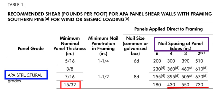
The table below rates plywood in terms of its ability to resist earthquakes and is from APA Research Report 154. The table is still part of the building code.
Below are some more detailed instructions on how to read this important table.
Below Panel Grade boxed in blue we see the panel grade is STRUCTURAL 1. This plywood grade is specific to shear walls and your contractor should be using it. Remarkably, Standard Plan A and all the other seismic retrofit guidelines allow another type of plywood call “rated sheathing” which is not optimal for shear walls. Shear walls made with rated sheathing are 12% weaker.
Under Minimal Nominal Thickness the thickness of the plywood is 15/32. This is usually referred to as half inch plywood.
Under Nail Size we are looking at 8d commons which are 0.131 inches in diameter and 2 1/2 inches long.
Under Nail Spacing at Panel Edges we see the spacing of the nails on the edges of the plywood in inches. It shows nails spaced 6 inches, 4 inches, 3 inches, and 2 inches apart.
Below that underlined in red we see the earthquake resistance of the plywood rated in pounds of resistance per linear foot. For example, under 4 inch nail spacing we see that the plywood can resist 430 pounds of earthquake force per linear foot of plywood, if the nails are 3 inches apart, the plywood can resist 550 pounds per linear foot, and if the nails are 2″ apart on all the edges, the plywood can resist 730 pounds per linear foot. Because Standard Plan A does not use structural 1 plywood its plywood capacity is only 380 pounds per linear foot while structural 1 plywood can resist 430 lbs. of earthquake when nailed 4″ apart on the edges.
We try to nail our plywood a minimum of 3″. If circumstances allow we try to put them 2″ apart. If we think the building inspector will be looking we put the nails 4″ apart. This is a case where building departments insist we do it wrong.
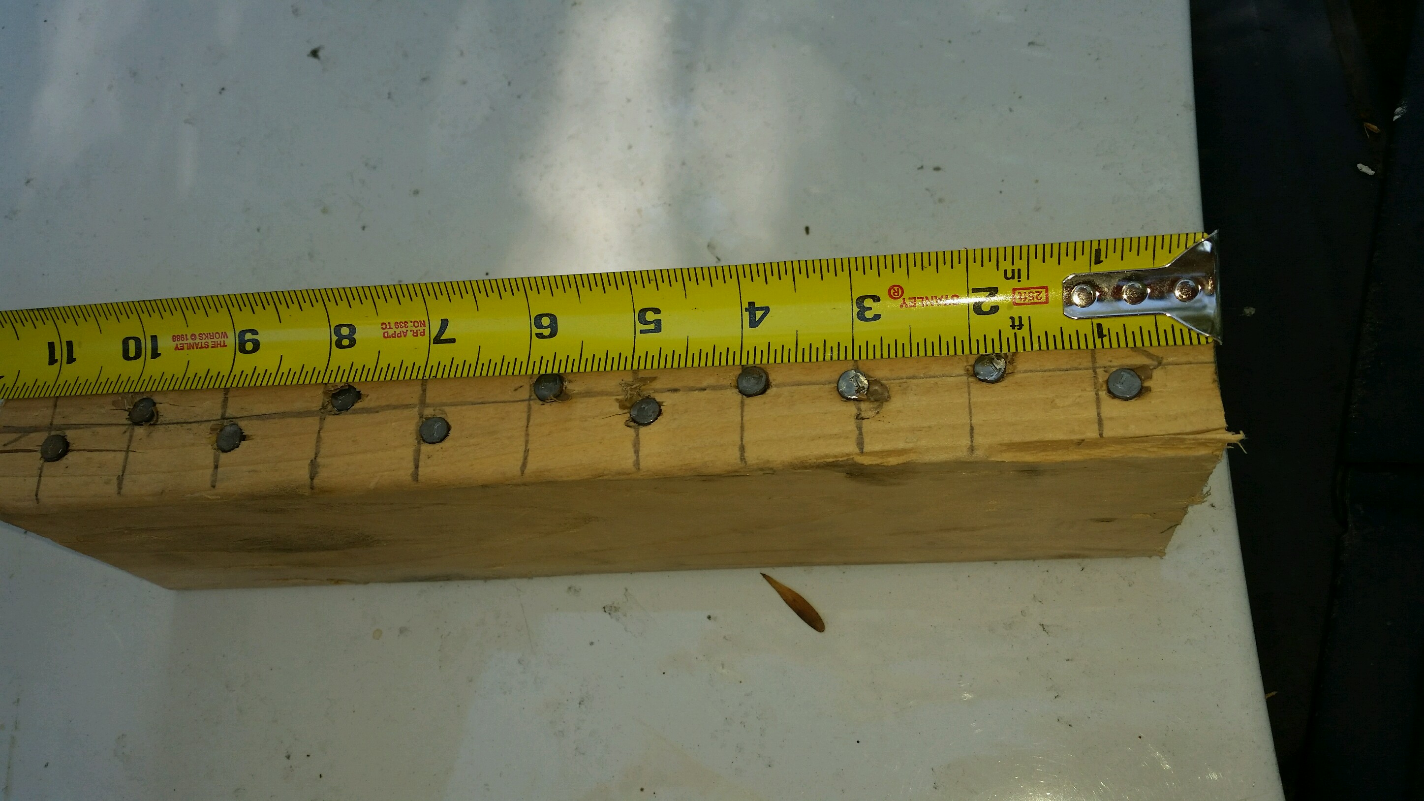
Block of wood with nails 1″ apart and no splitting
All retrofit guidelines require plywood edge nailing that is 4″ apart. This is done even though plywood nailed at 2″ apart will double the earthquake resistance of the plywood and the earthquake resistance of the retrofit.
Why Are The Retrofit Guidelines Irrational?
Wood quality varies from house to house. Before nailing the plywood 3″ apart or less, try nailing into some bare studs that don’t have plywood on them to make sure the wood can handle it.
What is Wrong With Standard Plan A Plywood Nailing?
The first column shows us the earthquake resistance of Standard Plan A’s plywood nailing after it was revised in 2008. The

How do Plywood Shear Walls Fail?
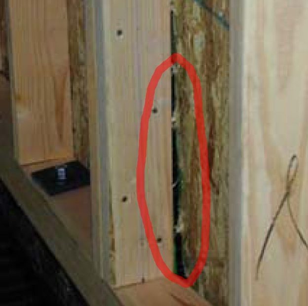
It is in the nails. If the shear wall resistance matches or exceeds the force it is supposed to resist, the plywood and nails will not move. For example, if we designed a shear wall to resist 10,000# of force, and it was hit by 10,000# of earthquake force, the nails and plywood remain exactly as they had been installed.

If the earthquake forces exceed the strength of the plywood-let’s say the plywood is nailed to resist 10,000# of force-and that plywood tries to resist 15,000# of force, you will get nail pull out as circled in red.
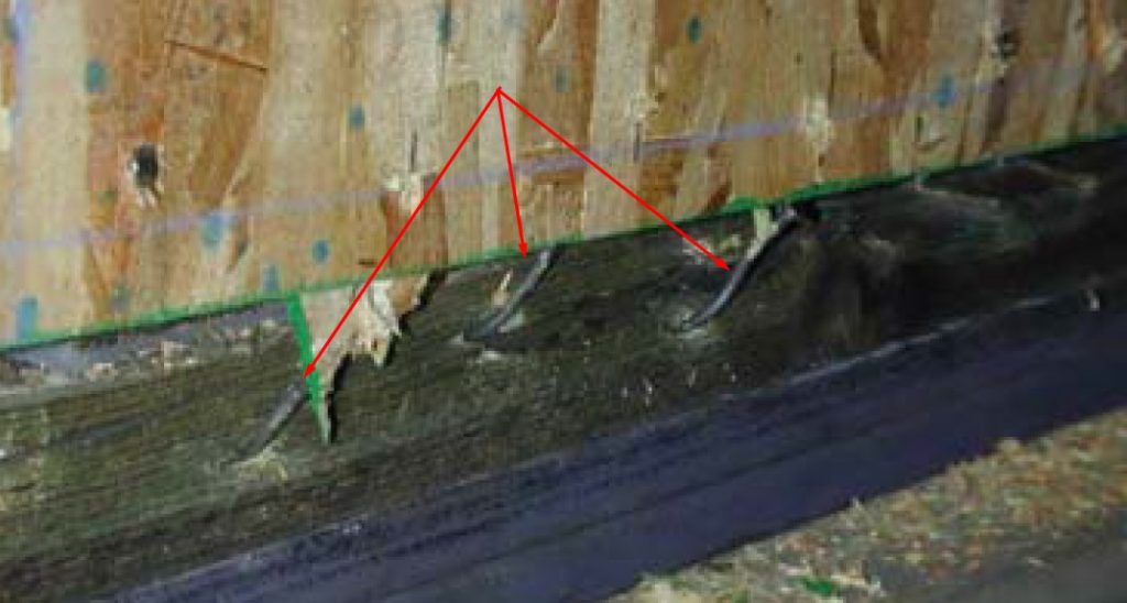
 If you nail the plywood to resist 10,000# of force and it must resist 20,000# of force, you will get nail punch out as shown below.
Non-Conventional Shear Walls are Sometimes Vital to a Good Seismic Retrofit
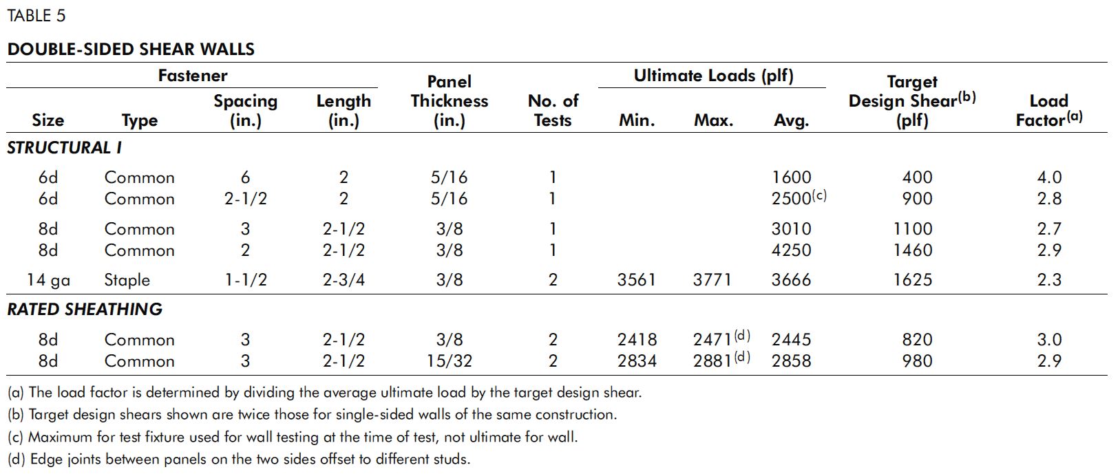
Double sided shear walls are useful when space for a shear wall is limited, and a new shear wall is required. By using a double-sided shear wall one can have 6 linear feet of foundation, install a 6-foot-long shear wall on each side, achieve the strength of 12 linear feet of shear wall that normally would have taken 12 linear feet of foundation.
Further on in the report it states:
“Typical failure of these walls was in compression and crushing of the lumber framing where the end studs bore against the bottom and top plates. The designer should carefully consider column buckling (snapping like a pencil) of the end framing members and bearing on the bottom plate in order to transmit these forces in compression to the foundation and in tension to hold-downs. In some cases, it may be desirable to stop the plate short of these end studs and allow the end studs to bear directly upon the foundation. In light of this, the designer should carefully consider column buckling of the end framing members (they can buckle and snap). This is done by carefully sizing the end framing members, reinforcing them with steel, or having the end studs bear directly on the foundation.”
The Most Technical Parts of Building Retrofit Shear Walls
This is more of a deflection issue (lateral movement of the top of the shear wall) rather than a strength issue. 1/8” crushing of the end studs into the mudsill at the bottom plate can cause over 1″ of at the top on a narrow shear wall. The magnification factor is the height of the shear wall / width of the shear wall x the amount of mudsill compression. If the walls are too flexible, they will not resist much earthquake force when the whole house deforms (twists) because of the earthquake.
For example, if the end framing member studs on an 8-foot tall by 4-foot-wide shear wall crush the mudsill 1 inch, the deflection at the top will be 2 inches, which is significant. (8/4 = 2, x 1 inch compression = 2-inch movement.
Note that a normal shear wall has deflections at the top of the wall in the range of about 0.2 inches at their design loads, so you can see that a little crushing can cause big problems when a narrow shear wall is used in line with other conventional shear walls.
High-Capacity Shear Walls
APA Research Report 138 are the results of a series of experiments done by the APA. They tested strength of plywood floors. A plywood floor is the same as a shear wall placed horizontally and the values below are equivalent to the typical vertical shear wall.
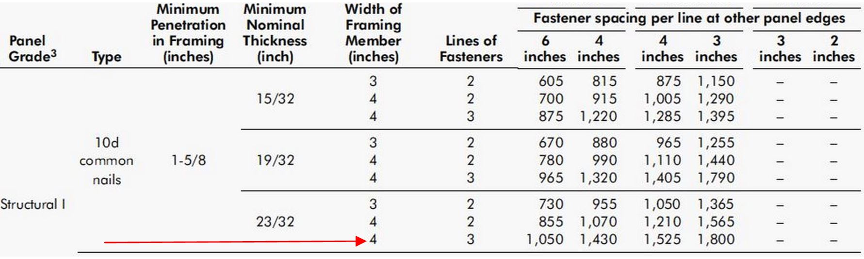
APA Research Report 138: describes tests prove show very high strength shear walls can be produced by using multiple rows of nails or staples in wood framing that is wider than the normal 1-1/2-inch-wide framing used in new construction. The capacity of stapled shear walls is at the bottom of this Table.
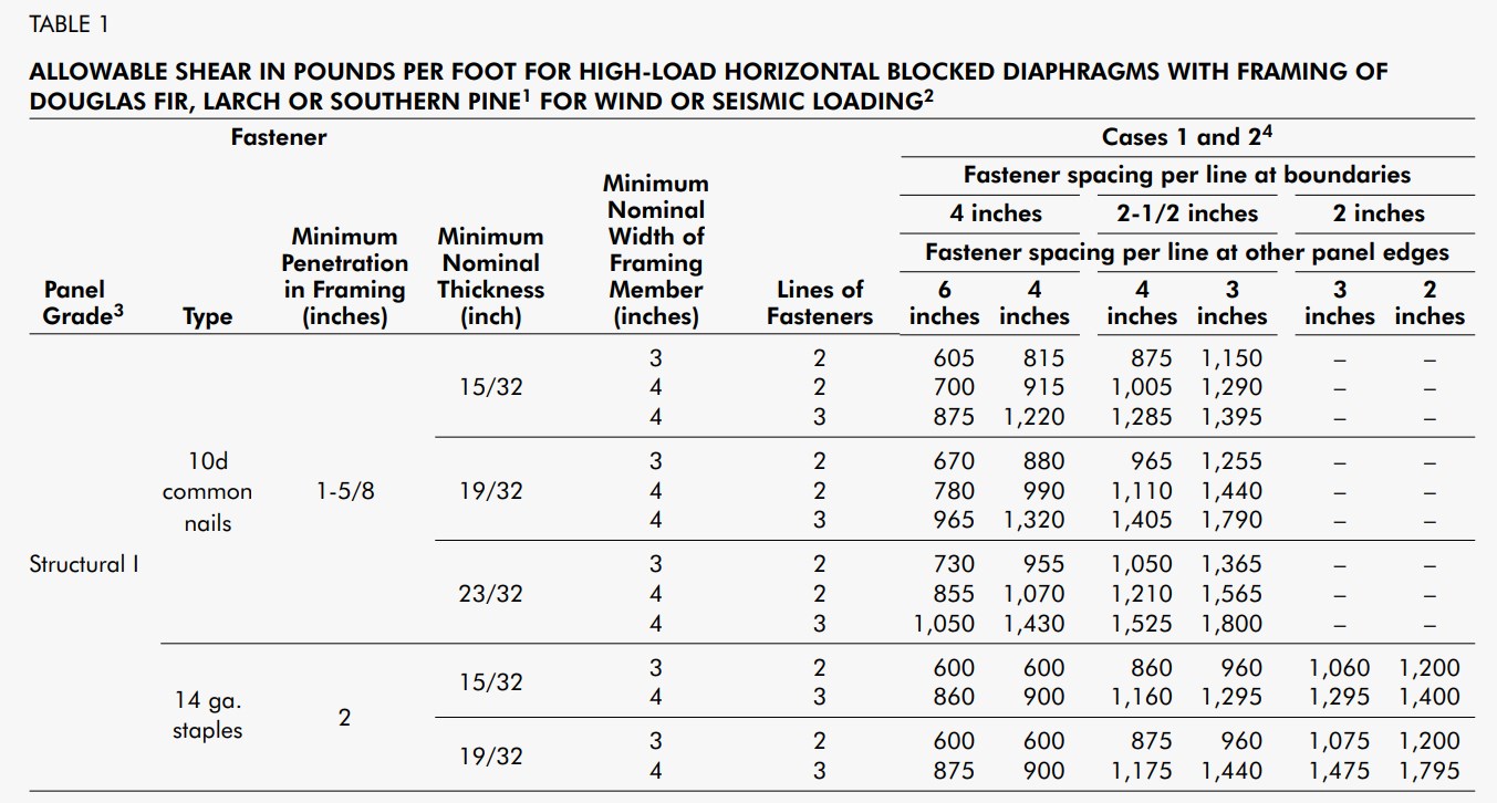
Looking at this table we are using:
(1) Structural I Plywood.
(2) Plywood that is 23/32 ” thick.
(3) The stud framing that is 4″ wide.
(4) The rows of nails. For example, 3 lines of fasteners means there are 3 rows of nails going up and down on the studs.
As you can see a shear wall built in this way can resist 1800 pounds of earthquake force and represents the strongest shear wall ever tested. Even though it has never been tested, a two-sided shear wall of this type could have an enormous ability to resist earthquakes. If old growth lumber is used even closer spacing of staples can provide an almost limitless shear wall capacity.
Overturning Forces in High-Capacity Shear Walls
A typical application would be typical building in San Francisco where much of the front lower story is taken up by a garage and the rest is taken up by a stair wall. In these circumstances, the front of the building is not connected to any foundation. This is also a preferred method in terms of effectiveness and often cost compared to moment columns.

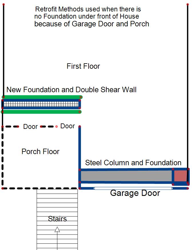
The next consideration is uplift or overturning forces.
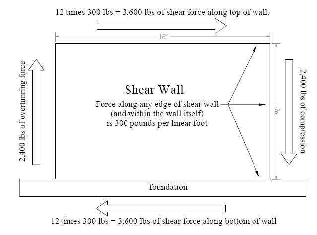
For example, if we build a high-capacity shear wall that can resist 1800# of force, the overturning force will be 8 x 1800# or 14,400# of overturning force. This kind of force will crush the mudsill and certainly break out the foundation. If the shear wall can resist 1900 pounds per linear foot of lateral earthquake force, it will also need to resist #15,200 pounds of overturning force. For this reason, proper sizing of hold-downs is critical. Under “Model No.” are the names of the hold-downs.

Stapled Shear Walls

Stapled shear walls are a consideration when one is concerned about the framing behind the plywood splitting.
The thickness of plywood has no bearing on shear wall strength except in the case of high-capacity shear walls. For these shear walls, plywood up to 19/32″ (3/4) thick was tested and it was discovered shear wall built in this manner were on average three times stronger than the shear walls found in the California Building Code.
This type of shear wall is extremely useful when one needs the strongest shear wall possible and a foundation strong enough to withstand this force. A typical application would be shear at the front or back of a long apartment house, such as those found in San Francisco, built on a new foundation with extensive steel reinforcing.
Stapled shear walls are a consideration when one is concerned about the framing behind the plywood splitting. According to the American Plywood Association, one should be able to double the number of nails and double the strength of the shear wall even though this was not tested. In other words, if you double the staple spacing, you should be able to double Target Shear.
Target shear is another name for “allowable load” which is the value the building code says you can use when designing a shear wall. “Ultimate Load” is the point at which the test specimen actually failed. “Load Factor” is the safety factor. Meaning if you have a shear wall that fails on the testing table (ultimate load) and divide this by the safety factor (load factor) the result is the “Target Design Shear” or allowable load. Scientists have a way of making everything more complicated than needs be.
Staples do not create high-capacity shear walls, but if spaced close enough together they are extremely stiff. This can be useful when designing a shear wall that will be working in tandem with other shear walls made of a stiffer material, such as plaster.
Plywood to Plywood Connections

In this test, plywood was stapled to plywood to see if how strong this connection would be. This is useful when it is necessary to attach to pieces of plywood together which is often the case when the contractor did not attach the first layer of plywood to the mudsill.

The next consideration is uplift or overturning forces. High-capacity shear walls must resist a tremendous about of overturning. For example, a high-capacity shear wall can create 14,400 pounds of force trying to lift the ends of the shear wall up off of the foundation. For this reason, proper sizing of hold-downs is critical.
Quality of Cripple Wall Framing
Older homes were built with old growth Douglas Fir and redwood that was centuries old. This wood has very different properties compared to wood grown on modern tree farms. The old wood is much denser and is very difficult to split compared to tree farm lumber. For this reason, the retrofit guidelines found in the International Existing Building Code, the Bay Area’s Standard Plan A, Seattle’s Project Impact, and the Los Angeles Retrofit Building Code only allow 8d nails spaced no closer than 4 inches apart. Old growth lumber should always be used whenever possible because it can easily be nailed with larger 10d nails 2 inches apart on the edges without splitting. 

If the initial shock does not collapse the cripple wall, an aftershock might. In the photo below, a man trying to prevent his already leaning cripple wall from fully collapsing in an aftershock.
You need the right type of Plywood
The two types of plywood available are Rated and Structural I, but for shear wall use the plywood must have 5 plies. Rated Plywood can be made of any species of wood while 10% stronger Structural I must be made of denser Southern Pine or Douglas Fir. Overall, it is not that big a deal if you use Rated instead of Structural I.
Avoid 3-PLY PLYWOOD
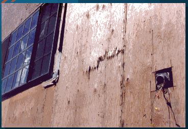
Plywood made with only 3 plies tore in the 1994 Northridge Earthquake and should not be used.
Shear walls made of 3 ply plywood tore in the Northridge Earthquake, so the City of Los Angeles downgraded the acceptable limits for 3-ply plywood to a maximum of #200 plf. On page 10 of the Wood-Frame Subcommittee Findings Report, published immediately after the Northridge Earthquake it says: “The performance of 3-ply construction has raised questions of its ultimate capacity. Horizontal tearing has occurred on some outer face plies above the inner ply seam. Values for all 3-ply panel construction were therefore reduced to 200lbs/ft maximum.”
Aspect Ratio-This is very technical
An aspect ratio is the ratio between the height and the width. For example, a shear wall that is 8 feet long and 4 feet wide has an aspect ratio of 2h/1w (the height is twice as long as the width). Normally it is written 2:1, or 2/1.
To use the values listed in Table 1 (see the chart at the beginning of this page), which is found in the building code, a shear wall must have a 2/1 aspect ratio or less. If the aspect ratio is greater than 2/1 but less than 3.5/1, the earthquake resistance measured in per linear foot of resistance, must be reduced by what is called a reduction factor.
This maximum 3.5/1 aspect ratio translates into an 8 ft. shear wall 27.5″ wide. Any narrower than this and you have a post, which is rated at zero.
The way you figure out the aspect ratio of a shear wall is to divide both the height and the width by the width. For example: if a shear wall is 64″ high/18″ wide, we divide both the height and the width by 18 to get a ration of 3.5/1. If the wall is 96″ tall then 96″/18″ = 5.3/1. At this point it is a post and not a shear wall.
Once we determine the aspect ratio, assuming it is less than 3.5/1, we use a reduction factor of twice the width 2w/h (height). So, if we have a shear wall that is 96″ tall and 30″ wide, the reduction factor is twice the w/h = 2 x 32/96 = 0.62. The number in the shear Table 1 is multiplied by this factor to get the reduced shear capacity of the narrow wall. In this case if the plywood can resist 870 pounds per linear foot, and the width of the shear wall is 2 1/2 feet, the capacity based on this table is 2.5 x 870 or 2,175#. The reduction factor is 0.66. 2,175# x 0.66 = 1,435#.
Once we determine the aspect ratio, assuming it is less than 3.5/1, we use a reduction factor of twice the width 2w/h (height). So, if we have a shear wall that is 96″ tall and 30″ wide, the reduction factor is twice the w/h = 2 x 30/96 = 0.62. The number in the shear Table 1 is multiplied by this factor to get the reduced shear capacity of the narrow wall. In this case if the plywood can resist 460 pounds per linear foot, and the width of the shear wall is 2 1/2 feet, the capacity based on this table is 2.5 x 460 or 1,150 lbs. The reduction factor is 0.62. 1,150lgs x 0.62 = 713# or 285 lbs. per linear foot.
Crushing of the Bottom Plates
1/8” crushing of the end studs into the mudsill at the bottom plate can cause over 1″ of at the top on a narrow shear wall. The magnification factor is the height of the shear wall / width of the shear wall x the amount of mudsill compression. If the walls are too flexible, they will not resist much earthquake force when the whole house deforms (twists) because of the earthquake.
For example, if the end framing member studs on an 8-foot tall by 4-foot-wide shear wall crush the mudsill 1 inch, the deflection at the top will be 2 inches, which is significant. (8/4 = 2, x 1 inch compression = 2-inch movement.
Note that a normal shear wall has deflections at the top of the wall in the range of about 0.2 inches at their design loads, so you can see that a little crushing can cause big problems when a narrow shear wall is used in line with other conventional shear walls.
This is more of a deflection issue (lateral movement of the top of the shear wall) rather than a strength issue. 1/8” crushing at the bottom plate can be translated to over an inch of deflection at the top for a narrow shear wall. The magnification factor is the height of the shear wall / width of the shear wall. If the walls are too flexible, they will not resist much earthquake force when the whole house deforms (twists) because of the earthquake.


