Seismic Retrofit Building Codes From The Simple and Affordable 1997 UCBC to The Complex and Unaffordable FEMA P-1100/ICC 1300.
This is the longest page on this website and contains videos and text to compare 4 different design systems in use today:
- Engineered systems that use something close to Standard Plan A’s engineering calculations.
- Standard Plan A tabulated system which closely follows Standard Plan A’s calculations.
- Another tabulated and completely unaffordable system titled ICC 1300 (currently titled FEMA P-1100).
- And Appendix Chapter A3 of the International Existing Building Code which was published shortly after the 1994 Northridge Earthquake as the Uniform Code For Building Conservation. I have discussed this guideline on another webpage.
None of these guidelines can be understood without first looking at the terminology, hardware, and methods used for cripple wall retrofits. That information is in this short video.
This next video illustrates how these components are used in a simple engineered system. This is important because the systems that use tables are based on similar engineering.
As noted in the video, engineered systems begin by determining the base shear. Base shear is the anticipated shear force at the base of a house where the base of the house (floor) sits on the foundation.
Once we know the base shear, we can figure out how many bolts, linear feet of plywood, and shear transfer ties (these connect the floor to the bolted mudsill) will be needed to keep the house on its foundation.
Here is another 6-minute video that further explains how this formula is used when developing a retrofit strategy. If the previous video was clear there is no need to watch this video. I can’t overemphasize the importance of engineering. Once you understand the engineering, you will be able to design any retrofit.
The formula for base shear for Standard Plan A V=0.186W where W is the weight of the building. In the Guidelines for Seismic Retrofit of Existing Buildings, the base shear is 0.146W, and for FEMA DR-4193 it is 0.130W. For some ICC 1300’s base shear is not defined in the guideline and is based on computer modeling rather than empirical evidence and the building code.
However, someone I know who helped write this guideline told me ICC 1300 uses a base shear of ~0.375W based on computer modeling. As we shall see, the use of computer modeling has a big impact on cost.
The anticipated ground acceleration varies depending on the proximity to the fault. The closer the fault, the greater the ground acceleration. Engineers call this the Near Source Factor and use it when determining base shear.

QUOTATION FROM STANDARD PLAN A CALCULATIONS.
Soil type and a Na of 1.3 plus some other factors produced Standard Plan A’s base shear of 0.186W. If you look through the calculations, you will find numerous locations where base shear is specified and looks like this.

The Modified Mercalli Scale
The Modified Mercalli Scale (MMS) uses fault proximity and soil type to assign a house a certain shaking zone.
To find out how close your house is to the fault go to https://earthquake.usgs.gov/education/haywardfault/ and click on “Hayward Fault Map and Tour” and type your address in the search box on the upper left and click on the search icon.
Each zone represents a degree of shaking intensity. Understandably, the amount a house shakes determines how much damage there will be. The relevant shaking zones in the MMS for the Bay Area extend from severe shaking (zone VIII) to violent shaking (zone IX), and finally to extreme shaking (zone X+). Fortunately, X+ is not forecast for the Hayward Fault unless the earthquake is larger than geologic records predict.
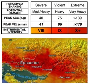
SHAKING INTENSITY AND MERCALLI SCALE
The USGS predicts a large 6.8 – 7.0 earthquake on the Hayward Fault. Once a conversion is made from Richter Scale to Modified Mercalli Scale we see that the houses closest to the fault (2km or less) are in zone IX. In other words, shaking intensity IX is as bad as it can get.; we can simply ignore the statistics for zone X+.

COMPARISON OF RICHTER AND MERCALLI SCALES.
Below are some statistics published by the Association of Bay Area Governments in “Shaken Awake!”, a study financed by the National Science Foundation. In this study, scientists looked at damage from both the Northridge and Loma Prieta Earthquakes to forecast probable damage to the Bay Area’s housing stock using the Modified Mercalli Scale.

PERCENTILE OF BUILDINGS RED-TAGGED IN SEISMIC ZONE IX.
Based on this table found on page 68 of Shaken Awake, 8.4 percent of the houses in zone IX built before 1940 will be deemed uninhabitable, and only 0.69 percent of the houses built after 1940 will suffer the same fate.
Applying Standard Plan A Engineering to a Seismic Retrofit
Standard Plan A was modeled information provided by the authors of Shaken Awake and the current director of the Seismological Society of American. It was agreed that the building code defined ground acceleration of 0.186Gs should be used.
The California Existing Building Code uses a ground acceleration of 0.146. Standard Plan A and FEMA Dr-4193 use 0.186 and 0.130 respectively.

Using empirical evidence of damage from the Northridge and Loma Prieta earthquakes, the vulnerability of the housing stock is as follows: steep hillside homes are the most vulnerable homes, next are older homes with living area above a garage, next are two-story homes with wood siding, then one-story homes with wood siding, then two-story stucco homes, and finally one-story stucco homes. Public policy should be prioritized with this in mind.
Remarkably, ICC 1300 and the other seismic retrofit guidelines assume stucco houses are the most vulnerable and make no distinction between houses built before and after 1940. The video below illustrates the resilience of stucco homes and why they are the least vulnerable.
Retrofits Using Standard Plan A’s Calculations.
In the following example, we will design a retrofit for a 1,350 house with wood siding, a comp shingle roof, and sheetrock walls using Standard Plan A’s calculations. In these calculations, the base shear is 0.186 x W, where W is the weight. You will find reference to 0.186W on numerous pages in the original calculations.
In order to design our retrofit, we need to know the earthquake resistance of the retrofit components as well as the weight of the house. The table on the left tells us how much a house weighs per square foot if they are built with certain construction materials. The table on the right tells us how much earthquake force some of the common retrofit hardware and plywood can resist. “Psf” means per square foot.
For example, a single-story house with a shingle roof, horizontal wood siding, and sheetrock inside weighs 34 lbs. per square foot and qualifies this house as being “light construction” as opposed to “heavy construction” according to Standard Plan A’s calculations.
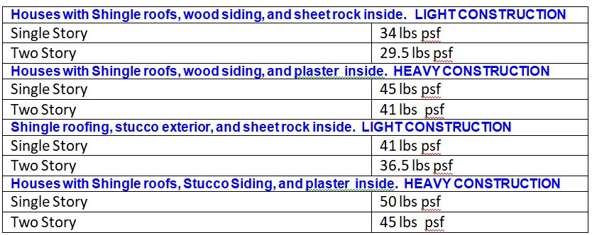
HOUSE WEIGHTS.
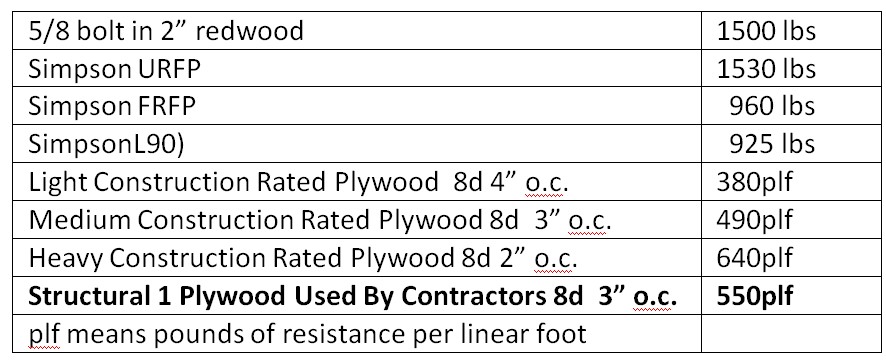
COMPONENT PRICING.
The weight of the house (W) = 1,350 square feet x 34 pounds per square foot or 45,900 lbs.
Multiply that by the 0.186 ground acceleration and we get a base shear of 8,536 lbs. Divide that by 2 because half the force will go on one side of the house and half the force on the other side. We need to resist 4,268 lbs. of force on each side.
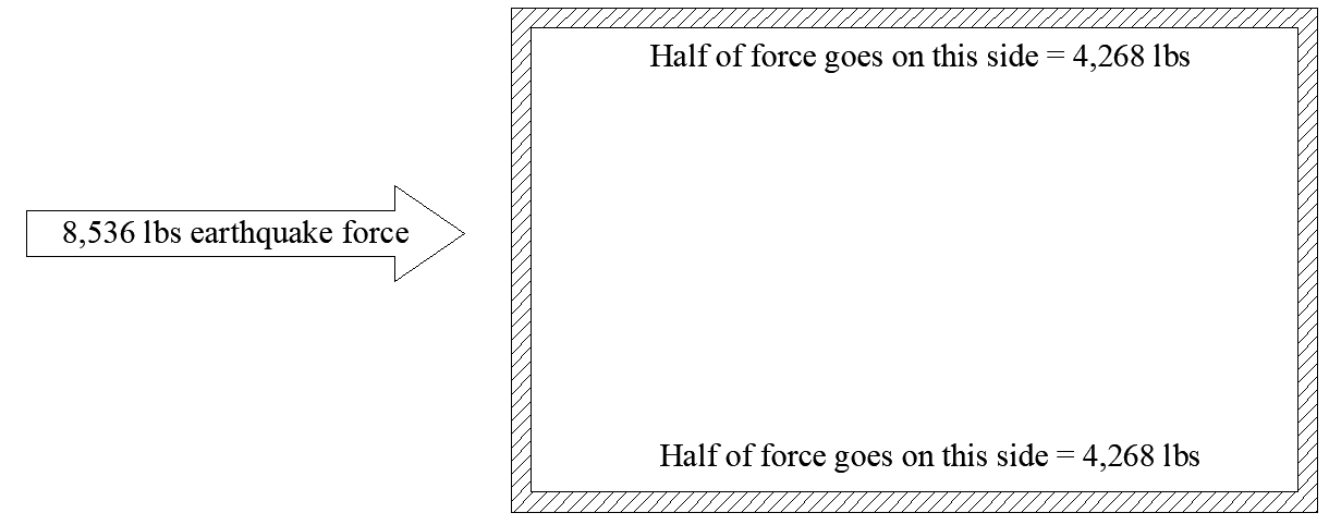
EQUAL RESISTANCE TO EARTHQUAKE FORCE ON EACH SIDE OF HOUSE.
This is what an engineered design looks like when using Standard Plan A’s calculations and its base shear of 0.186W.

STANDARD PLAN A CALCULATED DESIGN.

SUMMARY OF HARDWARE AND PLYWOOD COMPONENTS REQUIRED WHEN USING STANDARD PLAN A’s CALCULATIONS ARE USED ON A 1,350sf HOUSE. 550plf MEANS 550 POUNDS OF EARTHQUAKE RESISTANCE PER LINEAR FOOT OF PLYWOOD .
In order for this retrofit to be successful, all 3 parts of the retrofit must resist 4,268lbs of earthquake force. Notice how the shear resistance on each wall line for each component is approximately the same: i.e., 4,500 lbs. in bolts, 4400 lbs. in plywood, and 4625 lbs. in L90s. In doing this each of the 3 possible failure points can now withstand the anticipated 4,268 lbs. of force plus a little bit more. Doing more than this is a waste of money. Anything less than that and the retrofit might fail.
[/one_half]
Standard Plan A’s Tabulated System
The Standard Plan A Committee took these house weights and base shear and created a simple paint-by-numbers table called the REINFORCEMENT SCHEDULE which people could use rather than doing the multiplication and division we just looked at.
When we look at the second column titled TOTAL FLOOR AREA under GENERAL INFORMATION, we see that a 1350 square house square foot house lands between 1200 square feet and 1500 square feet. This system is designed such that when the actual square footage lands between two floor sizes, the larger size must be used. In other words, we need to use the requirements for a 1500 square foot house as highlighted in yellow.
Looking at the REINFORCEMENT SCHEDULE we see that a 1500 light construction house requires 17’4″ of plywood, 6 bolts, and 11 L90s on each side for a TOTAL of 24-5/8″ bolts, 44 L90s, and 68 linear feet of plywood as illustrated in the table below.
Let’s see what happens when we apply the REINFORCEMENT SCHEDULE to our sample 1350 square foot light construction house.
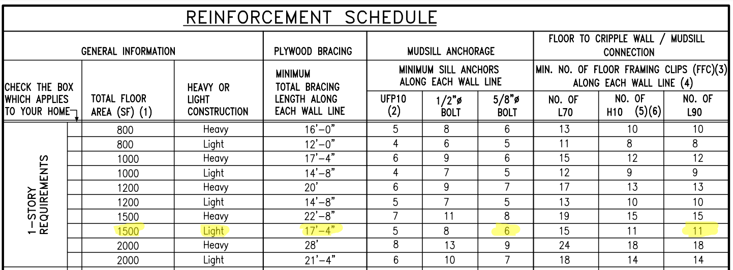
STANDARD PLAN A TABLE TELLS US HOW MANY BOLTS, L90s, AND LINEAR FEET OF PLYWOOD ARE NEEDED FOR CERTAIN SIZED AND WEIGHT CLASSES OF HOUSES. THE HIGHLIGHTS SHOW US WHAT IS NEEDED FOR A 1,350sf LIGHT CONSTRUCTION HOUSE.
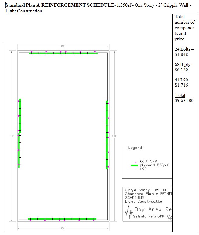

QUANTITIES AND EARTHQUAKE RESISTANCE OF HARDWARE WHEN USING STANDARD PLAN A’S REINFORCEMENT SCHEDULE. THE ACTUAL RESISTANCE OF A 5/8 BOLT IS 1,550LBS AND AN L90 600LBS. STANDARD PLAN A GOT IT WRONG.
Hey, what gives? Why are so many more retrofit components needed when using the REINFORCEMENT SCHEDULE than with the calculations?

COST AND QUANTITY COMPARISON BETWEEN STANDARD PLAN A AND ITS REINFORCEMENT SCHEDULE.
The main source of this problem is that the hardware values used in Standard Plan A’s CONNECTOR CAPACITY table are wrong. Standard Plan A lists 5/8 bolts as having 1170 pounds of earthquake resistance; 1550 lbs. is the actual value.
I can tell you engineers love “safety factors” which means “In case I screwed up on my calculations if I simply add 50% more components than my calculations say I need, it will work for sure.” It appears this philosophy was baked into the table. The problem is the cost also goes up 50% and the number of people who use it also drops 50%. In this case, they added 38% more components.
All hardware and plywood already have a built-in safety factor. For example, they will test an L90 and discover it fails when 2,775 lbs. of lateral force are applied to it. They then divide that by 3 to get 925#. The basic theory is that if the contractor screws up the installation or the hardware or nails are defective it will still resist 925#. Engineers take that number and do the same thing all over again so that in the end a retrofit can be outrageously expensive.

INCORRECT EARTHQUAKE RESISTANCE VALUES IN STANDARD PLAN A’s CONNECTOR CAPACITY TABLE.
When we use the correct bolt values, we only need 5 bolts on each wall, not 6. The L90 in the CONNECTOR CAPACITY TABLE is listed as only having 600 pounds of earthquake resistance, the actual value is 925 lbs. If we use its actual value, we need 7 L90s on each wall, not 11.
What happens if we use the actual values of the bolts, plywood, and shear transfer are used in Standard Plan A’s REINFORCEMENT SCHEDULE?
Standard Plan A’s plywood strength is designed to resist 380 lbs. per linear foot with 8d nails 4″ apart on the edges in rated plywood. Rated plywood is one grade lower than structural 1 plywood and has 10% less capacity with identical nailing.
17 linear feet of rated plywood with this nailing pattern can resist 6,640lbs. If 10d nails are used instead and spaced 2″ apart using structural 1 plywood, the required linear footage drops from 17′ linear feet to 8′ on each wall line with a capacity of 6,940lbs. In this case, the cost of the retrofit would drop significantly to $5,127 for the same amount of protection as the REINFORCEMENT SCHEDULE because there are fewer quantities of hardware and plywood.

QUANTITIES REQUIRED IF THE REINFORCEMENT SCHEDULE USES THE CORRECT L90 AND BOLT VALUES AND CLOSER PLYWOOD NAILING IS USED.
QUANTITIES REQUIRED IF ACTUAL VALUES FOR BOLTS, SHEAR TRANSFER TIES, AND BETTER NAILED PLYWOOD ARE USED.
FEMA Dr-4193
FEMA DR-4193 (I have no idea where they come up with these weird titles) was developed by FEMA shortly after the Napa earthquake in 2017. The construction details (these are drawings that show a contractor how to put something together) and its tables are very similar to ICC 1300. Its acknowledgments state it borrowed extensively from Standard Plan A.

THE DR-4193 TABLE TELLS US HOW MANY LINEAR FEET OF PLYWOOD, NUMBER OF BOLTS, AND L90S ARE NEEDED WHEN USING ITS TABULATED SYSTEM.
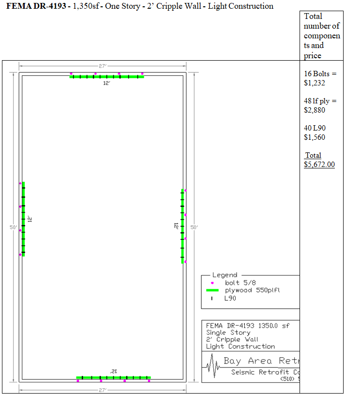
RETROFIT DESIGN WHEN FEMA 4193 IS APPLIED TO A 1350 SF LIGHT CONSTRUCTION HOUSE USING ITS INACCURATE L90 VALUE BORROW FROM STANDARD PLAN A.

QUANTITIES AND EARTHQUAKE RESISTANCE OF HARDWARE AND PLYWOOD WHEN THIS TABLE IS APPLIED TO A 1350 SF SINGLE-STORY HOUSE.
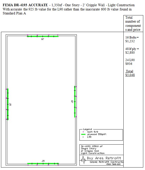
DESIGN WHEN THE ACCURATE 925 LBS VALUE FOR THE L90 IS USED RATHER THAN THE 600 LB VALUE FOUND IN DR-4193.

TABLE SHOWING WHAT HAPPENS WHEN THE ACCURATE L90 VALUE IS USED. THE COST OF THE RETROFIT IS REDUCED SIGNIFICANTLY.
ICC 1300
The International Code Council recently published a new seismic retrofit guideline called ICC 1300. This is the last guideline we will consider and see what happens when we apply it to the same 1350sf single-story light construction house.

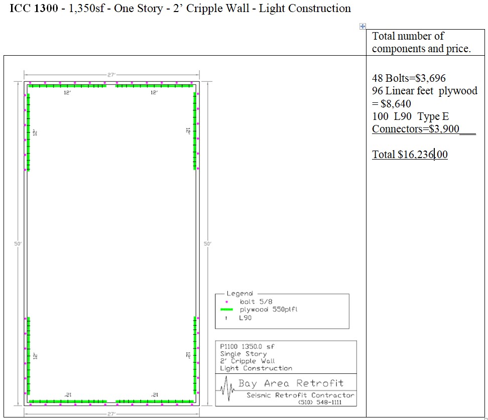
DESIGN WHEN USING ICC 1300 ON IN SINGLE-STORY LIGHT CONSTRUCTION HOUSE IN Sds 1.5.

NOTICE HOW THE RETROFIT HAS FAR MORE BOLTS AND SHEAR TRANSFER TIES AND DOUBLE THE AMOUNT OF PLYWOOD.
NOTICE HOW THIS RETROFIT HAS MORE THAN DOUBLE THE QUANTITIES OF HARDWARE AND TWICE AS MUCH PLYWOOD AS THE OTHER TWO SYSTEMS.
Summary

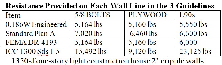
The capacities of each component more or less match in the engineered and tabulated methods and produce a balanced system. This is not the case with ICC 1300.
No Cripple Wall Retrofits
Here is a video on the engineering basis of Standard Plan A 0.186W retrofits. This video focuses on the engineering behind the retrofits of homes without a cripple wall.
The process is exactly the same as in cripple wall retrofits.
(W) = 1,350 square feet x 34 pounds per square foot or 45,900 lbs.
Multiply that by the 0.186 ground acceleration and we get a base shear of 8,536 lbs. Divide that by 2 because half the force will go on one side of the house and half the force on the other side. This is exactly what we did earlier.
EQUAL RESISTANCE TO EARTHQUAKE FORCE ON EACH SIDE OF HOUSE.
This is what an engineered design looks like when using Standard Plan A’s calculations and its base shear of 0.186W. V (base shear) = o.186 x 45,900lbs = 4,268 lbs.
Divide this by the foundation anchor strength of 1,530 lbs. This = We need 3 foundation anchors for a capacity of 4,590 lbs.
Divide this by the shear transfer tie strength of 925# and we get 4.6. We need 5 shear transfer ties for a capacity of 4,635 lbs.

ENGINEERED DESIGN USING STANDARD PLAN A CALCULATIONS AND 0.186W BASE SHEAR.
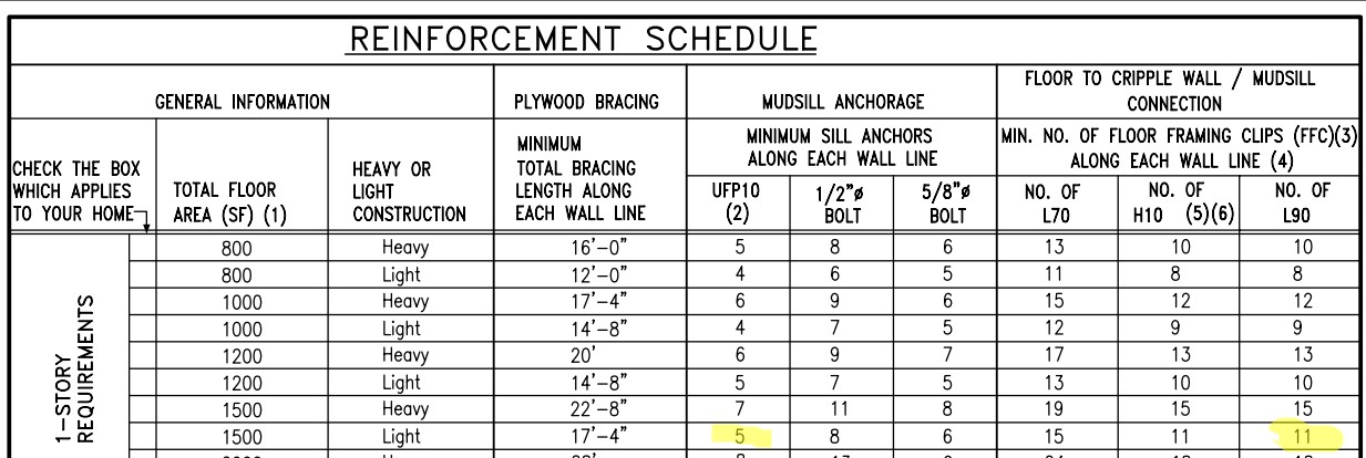
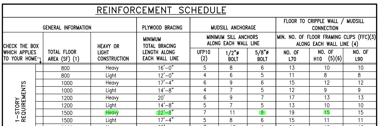
STANDARD PLAN A REINFORCEMENT SCHEDULE.

SEISMIC RETROFIT USING STANDARD PLAN As REINFORCEMENT SCHEDULE.
No Cripple Wall Retrofits in Dr-4193
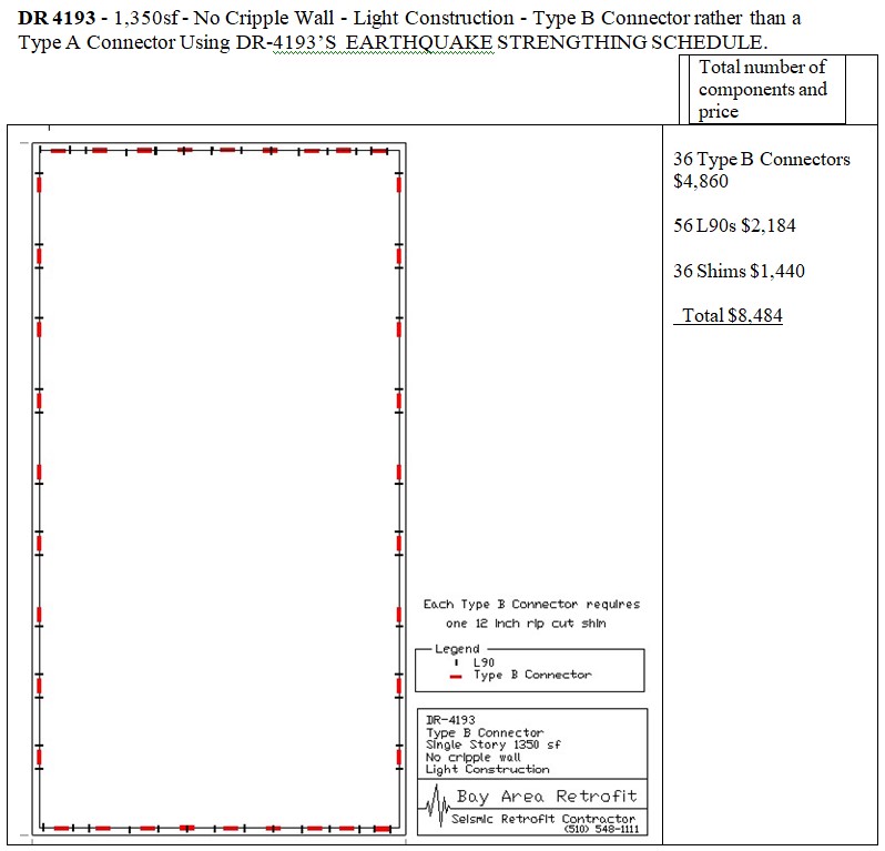
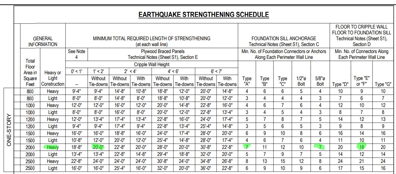
Notice how under FOUNDATION SILL ANCHORAGE there are Type A, Type B, and Type C Foundation Connectors. These are the 1,530 lb. Simpson Strong-Tie URFP, the 1065 lb. Simpson Strong-Tie FRFP (If 2 extra screws are used it can resist 1810 lbs.), and the 875 lb. USP SFA8 respectively.
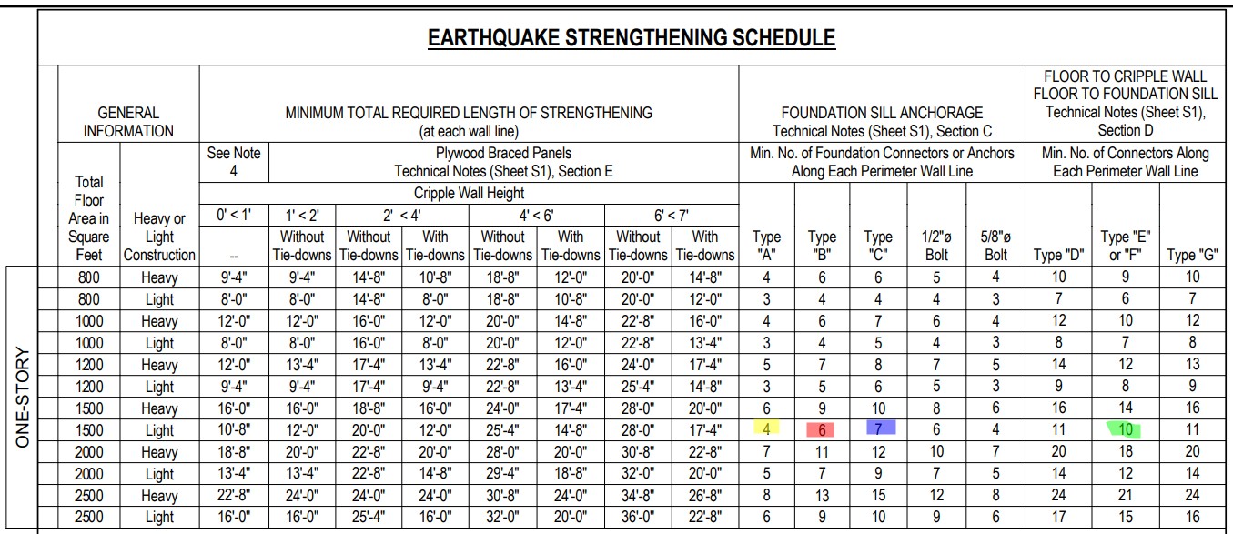
This table tells us we need 4-Type A Connectors plus 10 Type E Connectors. In Standard Plan A and FEMA DR-1493 the discontinued Simpson 1,340 lb. UFP10 is the Type A Connector. ICC 1300 uses the Simpson 1530 lb. URFP Type A Connector.
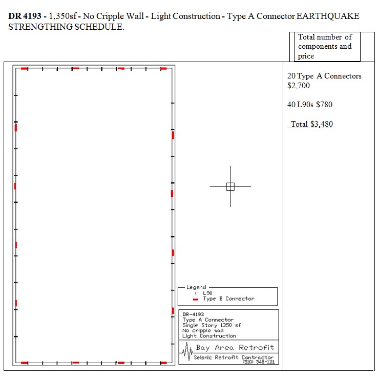
SEISMIC RETROFIT USING FEMA DR-1493’s REINFORCEMENT SCHEDULE.
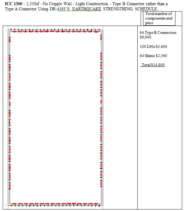
No Cripple Wall Retrofits in ICC 1300
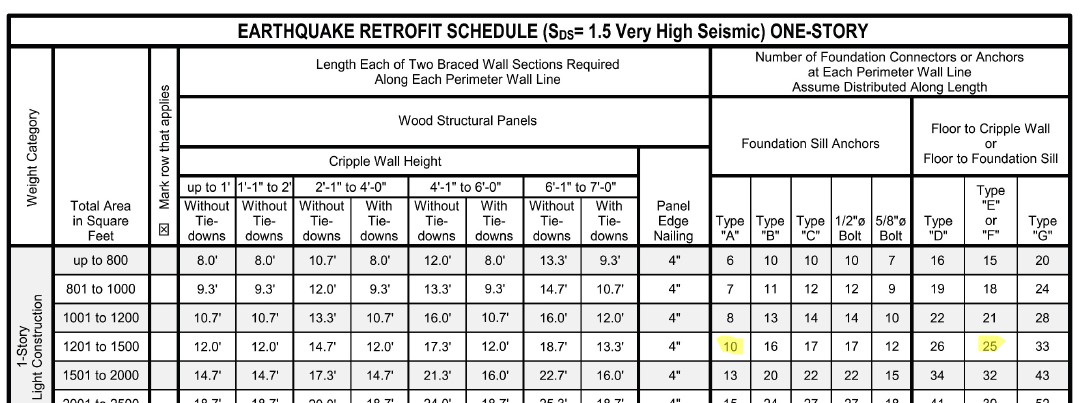
REINFORCEMENT SCHEDULE IN ICC 1300.
Seismic Design Category E
The table informs us that in Sds 1.5 we need 10-Type A Connectors and 25-Type E Connectors.
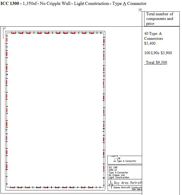
SEISMIC RETROFIT USING ICC 1300 Sds 1.5 VERY HIGH SHAKING INTENSITY.
Type B Connector
55
—

Standard Plan A Table
 —
—
—
 Seismic Design Category B through D1
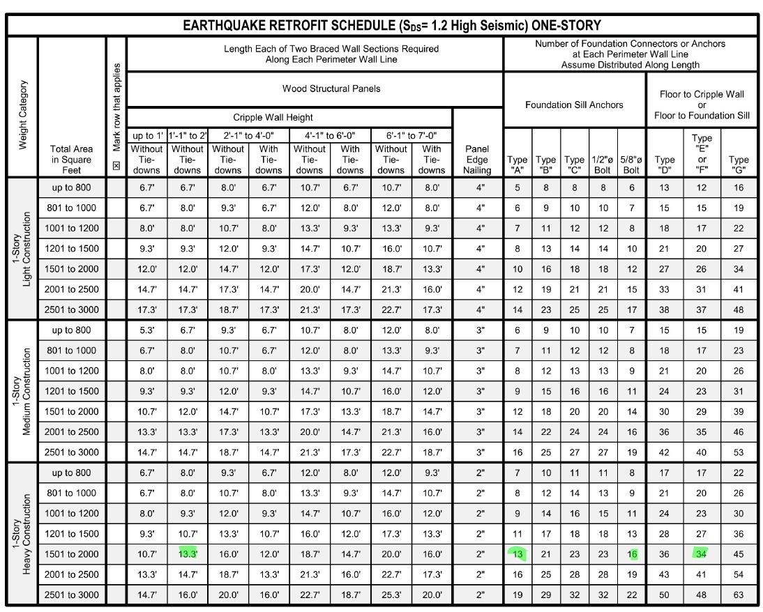
Seismic design category D2
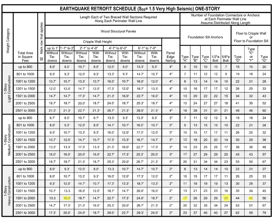
Seismic Design Category E
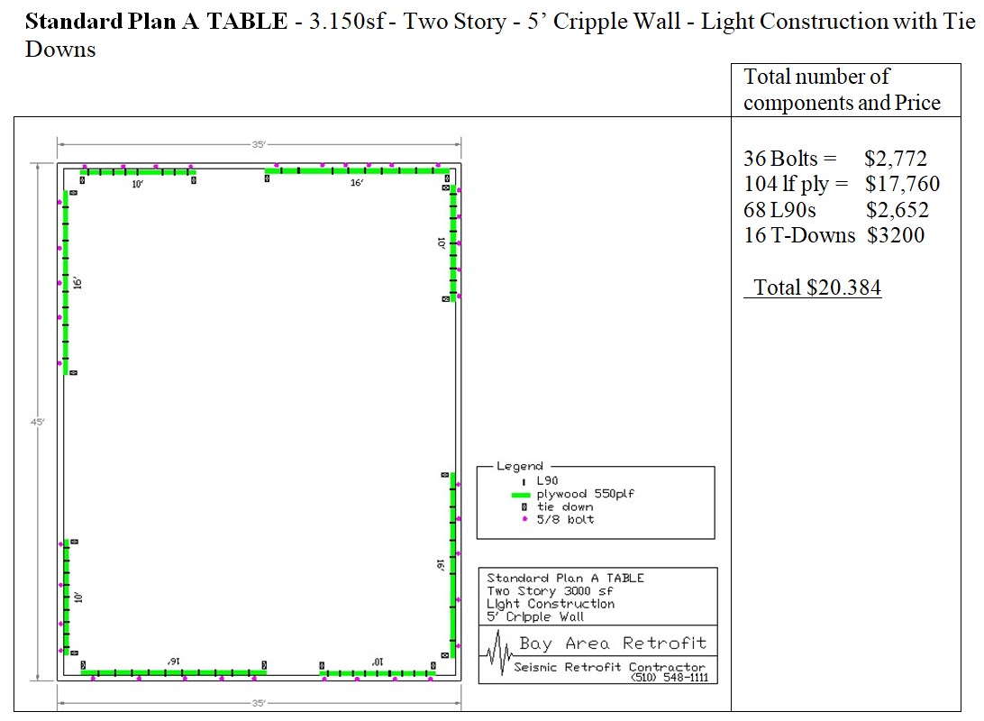
Now we are going to look at a few examples of two-story retrofits.
The design below is for a Standard Plan A engineered retrofit.
The design below is for an ICC 1300 retrofit for the same home.
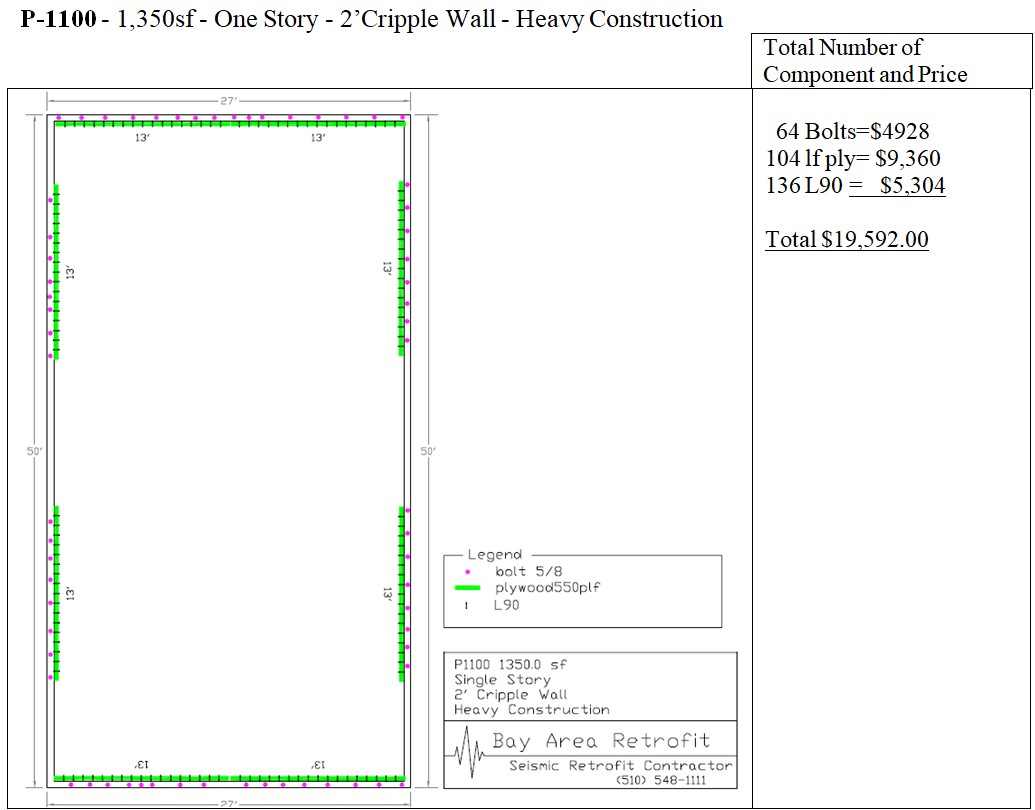
ICC 1300 RETROFIT FOR THE SAME HOME.
—

SUMMARY OF HARDWARE AND PLYWOOD REQUIREMENTS.

II

—

—

This webpage is for educational purposes only.


